Digital Logic
Logic Gates
Logic gates is an elementary building block of a digital circuit. Logic gates process signals which
represent true or false. Normally
the positive signals which
represent true or false. Most of the logic gates have two inputs
and one output.
AND Gate
AND gate
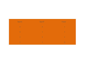
- The output of AND gate is TRUE only when all its inputs are FALSE(i.e. even if one input is FALSE, Output will be FALSE).
- Algebraic expression:
Output = AB or Output =A . B
OR Gate
OR Gate
- The output is true if input A or input B is TRUE.
- Algebraic expression:
Output
= A + B
NOT
Gate
NOT Gate
-
NOT
gate also know as an inverter.
- Output is TRUE when input A is FALSE, the output is the inverse of the input
- Algebraic expression :
A universal gate is a gate which can implement any Boolean
function without need to use any other gate type. There
are two universal gates NAND Gate and NOR gate.
NAND Gate
NAND Gate
- The NAND gate operates as an AND gate followed by a NOT gate.( NAND = NOT AND)
- The output of NAND gate is TRUE when any one of its input is FALSE (i.e. even if one input is FALSE, Output will be TRUE)
- Algebraic expression :
NOR Gate
NOR Gate
- The NOR
gate is a combination NOT gate followed by OR gate.
(NOR = Not OR)
- The output of NOR gate is TRUE when any all its inputs are FALSE (i.e. even if one input is TRUE, output will be FALSE).
- Algebraic expression :


0 comments:
Post a Comment